|

Home
Plans
Parts List
Building It
Tools
Prototype?
Images
Links
| |
|

|
|

|
 |
- The
frame of the Basic Project Engine was built up “board by board” from
individual parts made of basswood and mahogany.
- I
planned my cutting
carefully to make the best use of the materials.
- I
cut the
materials to length per the “cut list”, with a razor
saw.
- A
miter box was used when cutting the strip wood to
make sure the ends came out square.
|
|
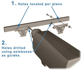
- Before assembling the frame,
I drilled
the mounting holes for the axleboxes with a 1/8” drill bit. I drilled
the holes marked "1" from dimensions found
on the plans.
- I
then used the axleboxes as
drilling guides for the others that are marked "2".
- This procedure
called for a little more precision than
some of the others, so took my time and worked carefully.
- This
ensured that the axles came out parallel to each
other and properly aligned relative to the frame.
|
 |
|
 |
- Next,
I
removed
the axleboxes and placed the wooden parts over the drawing for a trial
fit.
- Once
I was satisfied with the fit of the parts I was ready to glue the
frame together.
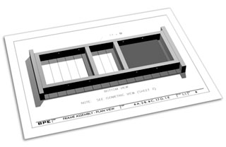
- I
built the frame directly on the plans
to ensure "squareness" of the final
assembly.
- I
used a piece of waxed paper to avoid gluing the
parts to the plan.
- It
tried to be sparing
with the glue because any excess would have caused problems later when I
stained and weathered the wood.
- I
started the assembly process by gluing together the frame
sills “B”, the cross braces “C”, and the end beams “A” with
5-minute epoxy.
- I
used epoxy because of its uperior strength and
durability. CA glues are brittle and do not
hold up nearly as well over time.
- I
placed weights on top of the pieces while the epoxy
cured.
|
|
- After the basic frame assembly
was done, I removed it from the
plans and layed the deck boards “D” onto the plan.
- I
staggered the ends of the boards slightly to give a more interesting look.
- I
then epoxied the frame to the deck material.
- The doubler plate
“E” was cut to size from the mahogany base plate that came with the
Midwest engine kit.
- It
is added to provide support for the engine after
the chain holes had been cut in the decking.
- I
glued the doubler plate to
the bottom side of the deck where indicated in the drawings.
- After
the glue had fully cured, I layed out the square holes for the drive chain.
- I
used a ¼” drill bit to start the holes, drilling
close to the lines.
- The holes
were then made square with careful application of a small
file.
- This
completed the assembly of the
frame.
|
 |
|
|
|
D I S C
L A I M E R
Please read:
|
|
Copyright
© 1994-2005 Michael Martin. All rights reserved.
Optimized for
viewing at 1024 x 768
This
page last updated: 02/10/05
|
|
|