|
 Start
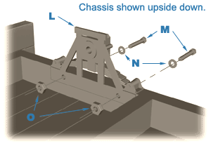
by bolting two axleboxes "L" to the left side of the
chassis with ½" long, 2-56 hex head brass machine screws "M"
and nuts "O". Use a washer "N" on the
head end of the screw to help prevent its digging into the wood. The
washer spreads the clamping force over a larger area. Start
by bolting two axleboxes "L" to the left side of the
chassis with ½" long, 2-56 hex head brass machine screws "M"
and nuts "O". Use a washer "N" on the
head end of the screw to help prevent its digging into the wood. The
washer spreads the clamping force over a larger area.
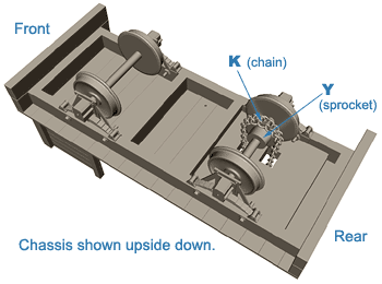
You can now place the
fully assembled wheelset into the front axlebox. (The front of the
locomotive is the end with the fuel bunker.) Place another axlebox over
the free end of the wheelset and bolt it into position. You will have
noticed that one of the wheelsets is not fully assembled. This is so
that you can slide the 15-tooth sprocket "K" onto the
axle. Before it will slide on, the hole in the sprocket needs to be
opened up with a 7/32" drill bit. Slide the sprocket onto the axle
and align it with the center of the holes in the deck by test fitting
the wheelset. After the sprocket is in position and the set screw is
tight, press the loose wheel onto the axle.
| Cut a section of ladder
chain to a length of 35 links. This will be the secondary drive chain
"Y", connecting the idler assembly to the drive wheels.
Using needle nose pliers (preferably round tip), open the links at one
end of the
chain. Study the chain carefully and you will see how to join the links
into a continuous chain. The chain must be passed through the holes in
the deck before joining the ends. Work carefully to produce a kink-free
chain. |
To complete the chassis
assembly, slide the wheelset with the sprocket through the chain and
place the axle into the axlebox. Place the remaining axlebox over the
free end of the wheelset and bolt it into position. The completion of the
rolling chassis marks the passing of a milestone. Take a moment to admire your
workmanship.
|
 |
|
